Monday, December 21, 2009

How Transformers Operates

Voltage Transformers

A Transformer does not generate electrical power, it transfers electrical power. A transformer is a voltage changer. Most transformers are designed to either step voltage up or to step it down, although some are used only to isolate one voltage from another. The transformer works on the principle that energy can be efficiently transferred by magnetic induction from one winding to another winding by a varying magnetic field produced by alternating current . An electrical voltage is induced when there is a relative motion between a wire and a magnetic field. Alternating current (AC) provides the motion required by changing direction which creates a collapsing and expanding magnetic field.

NOTE: Direct current (DC) is not transformed, as DC does not vary its magnetic fields
A transformer usually consists of two insulated windings on a common iron (steel) core.

The two windings are linked together with a magnetic circuit which must be common to both windings. The link connecting the two windings in the magnetic circuit is the iron core on which both windings are wound. Iron is an extremely good conductor for magnetic fields. The core is not a solid bar of steel, but is constructed of many layers of thin steel called laminations. One of the windings is designated as the primary and the other winding as the secondary. Since the primary and secondary are wound the on the same iron core, when the primary winding is energized by an AC source, an alternating magnetic field called flux is established in the transformer core. The flux created by the applied voltage on the primary winding induces a voltage on the secondary winding. The primary winding receives the energy and is called the input. The secondary winding is discharges the energy and is called the output.


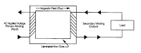
The primary and secondary windings consist of aluminum or copper conductors wound in coils around an iron core and the number of turns in each coil will determine the voltage transformation of the transformer. Each turn of wire in the primary winding has an equal share of the primary voltage . The same is induced in each turn of the secondary. Therefore, any difference in the number of turns in the secondary as compared to the primary will produce a voltage change.

Windings

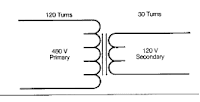
Step Down Transformers
If there are fewer turns in the secondary winding than in
the primary winding, the secondary voltage will be lower than the primary.


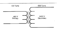
Step Up Transformers
If there are fewer turns in the primary winding than in the secondary winding, the secondary voltage will be higher than the secondary circuit.


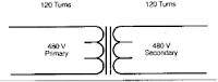
Note: The primary winding is the winding which receives the energy; it is not always the high-voltage winding. When the primary winding and the secondary winding have
the same amount of turns there is no change voltage, the ratio is 1/1 unity.


Common single-Phase Voltage Combinations:
120 x 240 to 120/240; 480 to 120/240; 4160 to 240/480
208 to 120/240; 480 to 120/240; 4160 to 240/480
277 to 120/240; 2400 to 120/240
240 x 480 to 120/240; 2400 to 240/480
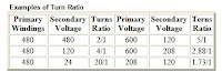
This relationship between the number of turns in the secondary and primary is often called the turns ratio (also referred to as the voltage ratio). It is customary to specify the turns ratio by writing the primary (input) number first.

Example: 30 to 1 is a step-down transformer, whereas a 1 to 30 would be a step-up transformer.


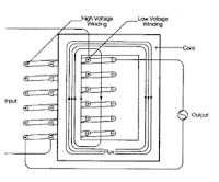
Winding Physical Location: In most transformers the high voltage winding is wound directly over the low voltage winding to create efficient coupling of the two windings.

Note: Other Designs may have the high voltage winding wound inside, side-by-side or sandwiched between layers of the low voltage winding to meet special requirements.

As stated previously, the voltage transformation is a function of the turns ratio. It may be desirable to change the ratio in order to get rated output voltage when the incoming voltage is slightly different than the normal voltage. As an example, suppose we have a transformer with a 4 to 1 turns ratio. With 480 volts input, the output would be 120 volts. Suppose the line voltage is less than the normal or 456 volts. This would produce an output voltage of 114 volts which is not desirable. By placing a tap in the primary winding, we could change the turns ratio so that with 456 volts input we could still get 120 volts output. This is called primary output voltage tap and standard transformers may have from two to six taps for the purpose of the adjusting to actual line voltages.


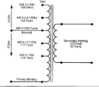
The above transformer has a tap (2) 2 1/2% below normal and one at 5% below , it is said to have (2) 2 1/2% full capacity below normal taps (FCBN). This would give a 5% voltage range. When the transformer has taps above normal as shown, they would be full capacity above normal (FCAN).

For Standardization purposes, these taps are in 2 1/2% or 5% steps. The taps are so designed that full capacity output can be obtained when the transformer is set on any of these taps. The universal tap arrangement used on many of our transformers ((2) 2 1/2% FCAN and (4) 2 1/2% FCBN) provides a 15% range of tap voltage adjustments.

Note: taps are only to be used for steady state input line variations. They are not designed to provide a constant secondary voltage when the input line is constantly fluctuating.

Series-Multiple Windings (Reconnectable Transformers)

To make the basic single-phase transformer move versatile, both the primary and secondary windings can be made in two equal parts. The two parts can be reconnected either in a series or in parallel . This provides added versatility as the primary winding can be connected for either 480 volts or 240 volts and the secondary winding can likewise be divided into two equal parts providing either 120 or 240 volts. (note: there will be four leads per winding brought out to the terminal compartment rather than two). Either arrangement will not affect the capacity of the transformer. Secondary windings are rated with a slant such as 120/240 and can be connected in a series for 240V or in a parallel for 120V or 240/120V (for 3-wire operation). Primary windings rated with an X such as 240X480 can operate in series or parallel but are not designed for 3-wire operation. A transformer rated 240X480V primary, 120/240V secondary could be operated in 6 different voltage combinations. Transformers are designed and cataloged by KVA ratings. Just as horsepower ratings designate the power capacity of an electric motor, a transformer’s KVA rating indicates its maximum power output capacity. The higher the transformers KVA rating for a specific input and output voltage, the larger transformer.
What does KVA mean? K= Abbreviation of the Greek word kilo, meaning ‘times 1000 V= Volts A= Amperes or Amp

Calculating KVA. There are only two formulas which you will need to know in order to calculate KVA:
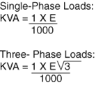
Where:
I = Amps
E = Volts
V3 = 1.732

For Example: A Transformer is supplying a three-phase load that draws 100 amps and requires a supply voltage of 208 volts. Therefore:


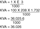
Thus, you must select a transformer with a capacity greater than 36.026 KVA.
Alternate Choice Use the FPT full load current rating chart and the secondary voltage on page 3 of the FPT catalog to establish the correct KVA.


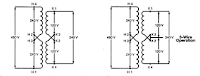
Connection: Primary in Series, Secondary in series.


Connection: Primary in series, Secondary in Parallel.
Connection: Primary in Parallel, Secondary in series


Connection: Primary in Parallel, Secondary in series.
Connection: Primary in Parallel, Secondary in Parallel.

Why We Use Transformers


Due to the high cost of transmitting electricity at low voltage and high current levels, transformers fulfill a most important role in electrical distribution systems. Utilities distribute electricity over large areas using high voltages, commonly called transmission voltages. Transmission voltages are normally in the 35,000 volt to 50,000 volt range. We know that volts times amps equals watts, and that wires are sized based upon their ability to carry amps. High voltage allows the utility to use small sizes of wire to transmit high levels of power, or watts. You can recognize transmission lines because they are supported by very large steel towers that you see around utility power plants and substations. As this electricity gets closer to its point of use it is converted, through the use of transformers, to a lower voltage normally called distribution voltage. Distribution voltages range from 2,400 to 25,000 volts depending upon the utility. Distribution lines are the ones that feed the pole mount and pad mount transformers located closest to your home or place of business. These transformers convert the distribution voltages to what we call utilization voltages. They are normally below 600 volts and are either single-phase or three-phase and are utilized for operating equipment, including light bulbs and vacuum cleaners in our homes, to motors and elevators where we work. This is the point at which the Dry-Type Distribution Transformer comes into play. It is used to convert the voltage provided by the utility to the voltage we need to operate various equipment.

Wednesday, December 16, 2009

Wireless Electricity (WiTricity)

Understanding what WiTricity technology is—transferring electric energy or power over distance without wires—is quite simple. Understanding how it works is a bit more involved, but it doesn’t require an engineering degree. We’ll start with the basics of electricity and magnetism, and work our way up to the WiTricity technology.

Electricity: The flow of electrons (current) through a conductor (like a wire), or charges through the atmosphere (like lightning). A convenient way for energy to get from one place to another!
Illustration of earth's magnetic field


An illustration representing the earth's magnetic field

Magnetism: A fundamental force of nature, which causes certain types of materials to attract or repel each other. Permanent magnets, like the ones on your refrigerator and the earth’s magnetic field, are examples of objects having constant magnetic fields.

Oscillating magnetic fields vary with time, and can be generated by alternating current (AC) flowing on a wire. The strength, direction, and extent of magnetic fields are often represented and visualized by drawings of the magnetic field lines.

Electric current flowing in a wire creates a magnetic field


As electric current, I, flows in a wire, it gives rise to a magnetic field, B, which wraps around the wire. When the current reverses direction, the magnetic field also reverses its direction.

Representation of the magnetic field created when current flows through a coil


The blue lines represent the magnetic field that is created when current flows through a coil. When the current reverses direction, the magnetic field also reverses its direction.

Electromagnetism: A term for the interdependence of time-varying electric and magnetic fields. For example, it turns out that an oscillating magnetic field produces an electric field and an oscillating electric field produces a magnetic field.

Magnetic Induction: A loop or coil of conductive material like copper, carrying an alternating current (AC), is a very efficient structure for generating or capturing a magnetic field.

If a conductive loop is connected to an AC power source, it will generate an oscillating magnetic field in the vicinity of the loop. A second conducting loop, brought close enough to the first, may “capture” some portion of that oscillating magnetic field, which in turn, generates or induces an electric current in the second coil. The current generated in the second coil may be used to power devices. This type of electrical power transfer from one loop or coil to another is well known and referred to as magnetic induction. Some common examples of devices based on magnetic induction are electric transformers and electric generators.

Energy/Power Coupling: Energy coupling occurs when an energy source has a means of transferring energy to another object. One simple example is a locomotive pulling a train car—the mechanical coupling between the two enables the locomotive to pull the train, and overcome the forces of friction and inertia that keep the train still—and, the train moves. Magnetic coupling occurs when the magnetic field of one object interacts with a second object and induces an electric current in or on that object. In this way, electric energy can be transferred from a power source to a powered device. In contrast to the example of mechanical coupling given for the train, magnetic coupling does not require any physical contact between the object generating the energy and the object receiving or capturing that energy.

A transformer uses magnetic induction to transfer power between its windings


An electric transformer is a device that uses magnetic induction to transfer energy from its primary winding to its secondary winding, without the windings being connected to each other. It is used to “transform” AC current at one voltage to AC current at a different voltage.

Resonance: Resonance is a property that exists in many different physical systems. It can be thought of as the natural frequency at which energy can most efficiently be added to an oscillating system. A playground swing is an example of an oscillating system involving potential energy and kinetic energy. The child swings back and forth at a rate that is determined by the length of the swing. The child can make the swing go higher if she properly coordinates her arm and leg action with the motion of the swing. The swing is oscillating at its resonant frequency and the simple movements of the child efficiently transfer energy to the system. Another example of resonance is the way in which a singer can shatter a wine glass by singing a single loud, clear note. In this example, the wine glass is the resonant oscillating system. Sound waves traveling through the air are captured by the glass, and the sound energy is converted to mechanical vibrations of the glass itself. When the singer hits the note that matches the resonant frequency of the glass, the glass absorbs energy, begins vibrating, and can eventually even shatter. The resonant frequency of the glass depends on the size, shape, thickness of the glass, and how much wine is in it.

Resonant Magnetic Coupling: Magnetic coupling occurs when two objects exchange energy through their varying or oscillating magnetic fields. Resonant coupling occurs when the natural frequencies of the two objects are approximately the same.

Two idealized resonant magnetic coils


Two idealized resonant magnetic coils, shown in yellow. The blue and red color bands illustrate their magnetic fields. The coupling of their respective magnetic fields is indicated by the connection of the colorbands.

WiTricity Technology: WiTricity power sources and capture devices are specially designed magnetic resonators that efficiently transfer power over large distances via the magnetic near-field. These proprietary source and device designs and the electronic systems that control them support efficient energy transfer over distances that are many times the size of the sources/devices themselves.

This diagram shows how the magnetic field can wrap around a conductive obstacle


The WiTricity power source, left, is connected to AC power. The blue lines represent the magnetic near field induced by the power source. The yellow lines represent the flow of energy from the source to the WiTicity capture coil, which is shown powering a light bulb. Note that this diagram also shows how the magnetic field (blue lines) can wrap around a conductive obstacle between the power source and the capture device.

Source: WiTricity.com

Wednesday, December 2, 2009

Effects at High Frequencies

A direct current flows constantly and uniformly throughout the cross-section of a uniform wire. An alternating current of any frequency is forced away from the wire's center, toward its outer surface. This is because the acceleration of an electric charge in an alternating current produces waves of electromagnetic radiation that cancel the propagation of electricity toward the center of materials with high conductivity. This phenomenon is called skin effect.

At very high frequencies the current no longer flows in the wire, but effectively flows on the surface of the wire, within a thickness of a few skin depths. The skin depth is the thickness at which the current density is reduced by 63%. Even at relatively low frequencies used for high power transmission (50–60 Hz), non-uniform distribution of current still occurs in sufficiently thick conductors. For example, the skin depth of a copper conductor is approximately 8.57 mm at 60 Hz, so high current conductors are usually hollow to reduce their mass and cost.

Since the current tends to flow in the periphery of conductors, the effective cross-section of the conductor is reduced. This increases the effective AC resistance of the conductor, since resistance is inversely proportional to the cross-sectional area in which the current actually flows. The AC resistance often is many times higher than the DC resistance, causing a much higher energy loss due to ohmic heating (also called I^2R loss).


Techniques for reducing AC resistance

For low to medium frequencies, conductors can be divided into stranded wires, each insulated from one other, and the relative positions of individual strands specially arranged within the conductor bundle. Wire constructed using this technique is called Litz wire. This measure helps to partially mitigate skin effect by forcing more equal current flow throughout the total cross section of the stranded conductors. Litz wire is used for making high-Q inductors, reducing losses in flexible conductors carrying very high currents at lower frequencies, and in the windings of devices carrying higher radio frequency current (up to hundreds of kilohertz), such as switch-mode power supplies and radio frequency transformers.

Techniques for reducing radiation loss

As written above, an alternating current is made of electric charge under periodic acceleration, which causes radiation of electromagnetic waves. Energy that is radiated represents a loss. Depending on the frequency, different techniques are used to minimize the loss due to radiation.

Twisted pairs

At frequencies up to about 1 GHz, pairs of wires are twisted together in a cable, forming a twisted pair. This reduces losses from electromagnetic radiation and inductive coupling. A twisted pair must be used with a balanced signalling system, so that the two wires carry equal but opposite currents. Each wire in a twisted pair radiates a signal, but it is effectively cancelled by radiation from the other wire, resulting in almost no radiation loss.

Coaxial cables

At frequencies above 1 GHz, unshielded wires of practical dimensions lose too much energy to radiation, so coaxial cables are used instead. A coaxial cable has a conductive wire inside a conductive tube, separated by a dielectric layer. The current flowing on the inner conductor is equal and opposite to the current flowing on the inner surface of the tube. The electromagnetic field is thus completely contained within the tube, and (ideally) no energy is radiation or coupling outside the tube. Coaxial cables have acceptably small losses for frequencies up to about 20 GHz. For microwave frequencies greater than 20 GHz, the losses (due mainly to the dissipation factor of the dielectric) become too large, making waveguides a more efficient medium for transmitting energy.

Waveguides

Waveguides are similar to coax cables, as both consist of tubes, with the biggest difference being that the waveguide has no inner conductor. Waveguides can have any arbitrary cross section, but rectangular cross sections are the most common. Because waveguides do not have an inner conductor to carry a return current, waveguides cannot deliver energy by means of an electric current, but rather by means of a guided electromagnetic field. Although surface currents do flow on the inner walls of the waveguides, those surface currents do not carry power. Power is carried by the guided electromagnetic fields. The surface currents are set up by the guided electromagnetic fields and have the effect of keeping the fields inside the waveguide and preventing leakage of the fields to the space outside the waveguide.

Waveguides have dimensions comparable to the wavelength of the alternating current to be transmitted, so they are only feasible at microwave frequencies. In addition to this mechanical feasibility, electrical resistance of the non-ideal metals forming the walls of the waveguide cause dissipation of power (surface currents flowing on lossy conductors dissipate power). At higher frequencies, the power lost to this dissipation becomes unacceptably large.

Fiber optics

At frequencies greater than 200 GHz, waveguide dimensions become impractically small, and the ohmic losses in the waveguide walls become large. Instead, fiber optics, which are a form of dielectric waveguides, can be used. For such frequencies, the concepts of voltages and currents are no longer used.

Utility Frequency (Power Frequency)

The line frequency (American English) or mains frequency (British English) is the frequency at which alternating current (AC) is transmitted from a power plant to the end user. In most parts of the world this is 50 Hz, although in the Americas it is typically 60 Hz. Precise details are shown in the list of countries with mains power plugs, voltages and frequencies.

During the development of commercial electric power systems in the late 19th and early 20th centuries, many different frequencies (and voltages) had been used. Large investment in equipment at one frequency made standardization a slow process. However, as of the turn of the 21st century, places that now use the 50 Hz frequency tend to use 220-240 V, and those that now use 60 Hz tend to use 100-120 V. Both frequencies co-exist today (some countries such as Japan use both) with no technical reason to prefer one over the other and no apparent desire for complete worldwide standardization.


Figure 1. The waveform of 230 volt, 50 Hz compared with 110 V, 60 Hz.

Unless specified by the manufacturer to operate on both 50 and 60 Hz, appliances may not operate efficiently or even safely if used on anything other than the intended frequency.

Operating factors

Several factors influence the choice of frequency in an AC system. Lighting, motors, transformers, generators and transmission lines all have characteristics which depend on the power frequency.

All of these factors interact and make selection of a power frequency a matter of considerable importance. The best frequency is a compromise between contradictory requirements. In the late 19th century, designers would pick a relatively high frequency for systems featuring transformers and arc lights, so as to economize on transformer materials, but would pick a lower frequency for systems with long transmission lines or feeding primarily motor loads or rotary converters for producing direct current. When large central generating stations became practical, the choice of frequency was made based on the nature of the intended load. Eventually the improvements in machine design allowed a single frequency to be used both for lighting and motor loads; a unified system improved the economics of electricity production since system load was more uniform during the course of a day.

Lighting

The first applications of commercial electric power were incandescent lighting and commutator-type electric motors. Both devices operate well on DC, but DC cannot be easily transmitted long distances at utilization voltage and also cannot be easily changed in voltage.

If an incandescent lamp is operated on a low-frequency current, the filament cools on each half-cycle of the alternating current, leading to perceptible change in brightness and flicker of the lamps; the effect is more pronounced with arc lamps, and the later mercury-vapor and fluorescent lamps.

Rotating machines

Commutator-type motors do not operate well on high-frequency AC since the rapid changes of current are opposed by the inductance of the motor field; even today, although commutator-type universal motors are common in 50 Hz and 60 Hz household appliances, they are small motors, less than 1 kW. The induction motor was found to work well on frequencies around 50 to 60 Hz but with the materials available in the 1890s would not work well at a frequency of, say, 133 Hz. There is a fixed relationship between the number of magnetic poles in the induction motor field, the frequency of the alternating current, and the rotation speed; so, a given standard speed limits the choice of frequency (and the reverse). Once induction motors became common, it was important to standardize frequency for compatibility with the customer's equipment.

Generators operated by slow-speed reciprocating engines will produce lower frequencies, for a given number of poles, than those operated by, for example, a high-speed steam turbine. For very slow prime mover speeds, it would be costly to build a generator with enough poles to provide a high AC frequency. As well, synchronizing two generators to the same speed was found to be easier at lower speeds. While belt drives were common as a way to increase speed of slow engines, in very large ratings (thousands of kilowatts) these were expensive, inefficient and unreliable. Direct-driven generators off steam turbines after about 1906 favored higher frequencies. The steadier rotation speed of high-speed machines allowed for satisfactory operation of commutators in rotary converters.

Direct-current power was not entirely displaced by alternating current and was useful in railway and electrochemical processes. Prior to the development of mercury arc valve rectifiers, rotary converters were used to produce DC power from AC. Like other commutator-type machines, these worked better with lower frequencies.

Transmission and transformers

With AC, transformers can be used to step down high transmission voltages to lower utilization voltage. Since, for a given power level, the dimensions of a transformer are roughly inversely proportional to frequency, a system with many transformers would be more economical at a higher frequency.

Electric power transmission over long lines favors lower frequencies. The effects of the distributed capacitance and inductance of the line are less at low frequency.

System interconnection

Generators can only be interconnected to operate in parallel if they are of the same frequency and wave-shape. By standardizing the frequency used, generators in a geographic area can be interconnected in a grid, providing reliability and cost savings.

History Of Power Frequency

Many different power frequencies were used in the 19th century. Very early isolated AC generating schemes used arbitrary frequencies based on convenience for steam engine, water turbine and electrical generator design. Frequencies between 16⅔ Hz and 133⅓ Hz were used on different systems. For example, the city of Coventry, England, in 1895 had a unique 87 Hz single-phase distribution system that was in use until 1906. The proliferation of frequencies grew out of the rapid development of electrical machines in the period 1880 through 1900. In the early incandescent lighting period, single-phase AC was common and typical generators were 8-pole machines operated at 2000 RPM, giving a frequency of 133 cycles per second.

Though many theories exist, and quite a few entertaining urban legends, there is little certitude in the details of the history of 60 Hz vs 50 Hz.


The German company AEG (descended from a company founded by Edison in Germany) built the first German generating facility to run at 50 Hz, allegedly because 60 was not a preferred number. AEG's choice of 50 Hz is thought by some to relate to a more "metric-friendly" number than 60. At the time, AEG had a virtual monopoly and their standard spread to the rest of Europe. After observing flicker of lamps operated by the 40 Hz power transmitted by the Lauffen-Frankfurt link in 1891, AEG raised their standard frequency to 50 Hz in 1891.

Westinghouse Electric decided to standardize on a lower frequency to permit operation of both electric lighting and induction motors on the same generating system. Although 50 Hz was suitable for both, in 1890 Westinghouse considered that existing arc-lighting equipment operated slightly better on 60 Hz, and so that frequency was chosen.[5] Frequencies much below 50 Hz gave noticeable flicker of arc or incandescent lighting. The operation of Tesla's induction motor required a lower frequency than the 133 Hz common for lighting systems in 1890. In 1893 General Electric Corporation, which was affiliated with AEG in Germany, built a generating project at Mill Creek, California using 50 Hz, but changed to 60 Hz a year later to maintain market share with the Westinghouse standard.


25 Hz origins

The first generators at the Niagara Falls project, built by Westinghouse in 1895, were 25 Hz because the turbine speed had already been set before alternating current power transmission had been definitively selected. Westinghouse would have selected a low frequency of 30 Hz to drive motor loads, but the turbines for the project had already been specified at 250 RPM. The machines could have been made to deliver 16⅔ Hz power suitable for heavy commutator-type motors but the Westinghouse company objected that this would be undesirable for lighting, and suggested 33⅓ Hz. Eventually a compromise of 25 Hz, with 12 pole 250 RPM generators, was chosen. Because the Niagara project was so influential on electric power systems design, 25 Hz prevailed as the North American standard for low-frequency AC.

40 Hz origins

A General Electric study concluded that 40 Hz would have been a good compromise between lighting, motor, and transmission needs, given the materials and equipment available in the first quarter of the 20th Century. Several 40 Hz systems were built. The Lauffen-Frankfurt demonstration used 40 Hz to transmit power 175 km in 1891. A large interconnected 40 Hz network existed in north-east England (the Newcastle-upon-Tyne Electric Supply Company, NESCO) until the advent of the National Grid (UK) in the late 1920s, and projects in Italy used 42 Hz. The oldest continuously-operating commercial hydroelectric power plant in the United States, at Mechanicville, New York, still produces electric power at 40 Hz and supplies power to the local 60 Hz transmission system through frequency changers. Industrial plants and mines in North America and Australia sometimes were built with 40 Hz electrical systems which were maintained until too uneconomic to continue. Although frequencies near 40 Hz found much commercial use, these were bypassed by standardized frequencies of 25, 50 and 60 Hz preferred by higher volume equipment manufacturers.

Standardization

In the early days of electrification, so many frequencies were used that no one value prevailed (London in 1918 had 10 different frequencies). As the 20th century continued, more power was produced at 60 Hz (North America) or 50 Hz (Europe and most of Asia). Standardization allowed international trade in electrical equipment. Much later, the use of standard frequencies allowed interconection of power grids. It wasn't until after World War II with the advent of affordable electrical consumer goods that more uniform standards were enacted.

In Britain, implementation of the National Grid starting in 1926 compelled the standardization of frequencies among the many interconnected electrical service providers. The 50 Hz standard was completely established only after World War II.

Because of the cost of conversion, some parts of the distribution system may continue to operate on original frequencies even after a new frequency is chosen. 25 Hz power was used in Ontario, Quebec, the northern USA, and for railway electrification. In the 1950s, many 25 Hz systems, from the generators right through to household appliances, were converted and standardized. Some 25 Hz generators still exist at the Beck 1 and Rankine generating stations near Niagara Falls to provide power for large industrial customers who did not want to replace existing equipment; and some 25 Hz motors and a 25 Hz electrical generator power station exist in New Orleans for floodwater pumps. Some of the metre gauge railway lines in Switzerland operate at 16⅔ Hz, which can obtained from the local 50 Hz 3 phase power grid through frequency converters.

In some cases, where most load was to be railway or motor loads, it was considered economic to generate power at 25 Hz and install rotary converters for 60 Hz distribution.Converters for production of DC from alternating current were larger and more efficient at 25 Hz compared with 60 Hz. Remnant fragments of older systems may be tied to the standard frequency system via a rotary converter or static inverter frequency changer. These allow energy to be interchanged between two power networks at different frequencies, but the systems are large, costly, and consume some energy in operation.

Rotating-machine frequency changers used to convert between 25 Hz and 60 Hz systems were awkward to design; a 60 Hz machine with 24 poles would turn at the same speed as a 25 Hz machine with 10 poles, making the machines large, slow-speed and expensive. A ratio of 60/30 would have simplified these designs, but the installed base at 25 Hz was too large to be economically opposed.

In the United States, the Southern California Edison company had standardized on 50 Hz. Much of Southern California operated on 50 Hz and did not completely change frequency of their generators and customer equipment to 60 Hz until around 1948. Some projects by the Au Sable Electric Company used 30 Hz at transmission voltages up to 110,000 volts in 1914.

In Mexico, areas operating on 50 Hz grid were converted during the 1970s, uniting the country under 60 Hz.

In Japan, the western part of the country (Kyoto and west) uses 60 Hz and the eastern part (Tokyo and east) uses 50 Hz. This originates in the first purchases of generators from AEG in 1895, installed for Tokyo, and General Electric in 1896, installed in Osaka.

Utility Frequencies in Use in 1897 in North America
Cycles Description
140 Wood arc-lighting dynamo
133 Stanley-Kelly Company
125 General Electric single-phase
66.7 Stanley-Kelly company
62.5 General Electric "monocyclic"
60 Many manufacturers, becoming "increasing common" in 1897
58.3 General Electric Lachine Rapids
40 General Electric
33 General Electric at Portland Oregon for rotary converters
27 Crocker-Wheeler for calcium carbide furnaces
25 Westinghouse Niagara Falls 2-phase - for operating motors

Even by the middle of the 20th century, utility frequencies were still not entirely standardized at the now-common 50 Hz or 60 Hz. In 1946, a reference manual for designers of radio equipment listed the following now obsolete frequencies as in use. Many of these regions also had 50 cycle, 60 cycle or direct current supplies.

Frequencies in Use in 1946 (As well as 50 Hz and 60 Hz)
Cycles Region
25 Canada (Southern Ontario), Panama Canal Zone(*), France, Germany, Sweden, UK, China, Hawaii,India, Manchuria,
40 Jamaica, Belgium, Switzerland, UK, Federated Malay States, Egypt, West Australia(*)
42 Czechoslovakia, Hungary, Italy, Monaco(*), Portugal, Romania, Yugoslavia, Libya (Tripoli)
43 Argentina
45 Italy, Libya (Tripoli)
76 Gibraltar(*)
100 Malta(*), British East Africa

Where regions are marked (*), this is the only utility frequency shown for that region.

Harmonics Resonance

Harmonics Resonance is a phenomenon which can occur in a power system. It can cause system instability or damage to electrical components such as capacitors and transformers. Harmonic resonance occurs when the inductive reactance and the capacitive reactance of the power system become equal.

However, as the order of the harmonics (frequency) increases, the inductive reactance increases while the capacitive reactance decreases.

At a particular frequency of harmonics, the inductive and capacitive reactances become equal and resonance sets in. Resonance can cause erratic conditions in the power systems such as transient high or low voltages, unexplained breakdown of equipment such as failure of transformer windings or failure of capacitor. Transient voltages generated by such harmonics resonance can also result in unexpected operation of relays and breakers.


The phenomenon of Harmonic Resonance should be borne in mind when modifying the system to add capacitors to improve the power factor or when adding new inductive loads such as motors, reactors, or transformers to existing systems containing capacitors.

The formula to determine the order of harmonic which may cause resonance is


where MVAsc is the impedance of the source and MVARcap is the reactive power drawn by the capacitors.Thus when a 20 MVAr capacitance is connected across a source of 1000 MVA, there will be a condition of resonance at the 7th Harmonic.

The possibility of harmonic resonance should be explored and eliminated during any modification/addition of loads in the power system.

AC Motor Construction

Three-phase AC induction motors are commonly used in industrial applications. This type of motor has three main parts, rotor, stator, and enclosure. The stator and rotor do the work, and the enclosure protects the stator and rotor.


Stator Core
The stator is the stationary part of the motor’s electromagnetic circuit. The stator core is made up of many thin metal sheets, called laminations. Laminations are used to reduce energy loses that would result if a solid core were used.


Stator Windings Stator laminations are stacked together forming a hollow cylinder. Coils of insulated wire are inserted into slots of the stator core.


When the assembled motor is in operation, the stator windings are connected directly to the power source. Each grouping of coils, together with the steel core it surrounds, becomes an electromagnet when current is applied. Electromagnetism is the basic principle behind motor operation.


Rotor Construction
The rotor is the rotating part of the motor’s electromagnetic circuit. The most common type of rotor used in a three-phase induction motor is a squirrel cage rotor. Other types of rotor construction is discussed later in the course. The squirrel cage rotor is so called because its construction is reminiscent of the rotating exercise wheels found in some pet cages.


A squirrel cage rotor core is made by stacking thin steel laminations to form a cylinder.


Rather than using coils of wire as conductors, conductor bars are die cast into the slots evenly spaced around the cylinder. Most squirrel cage rotors are made by die casting aluminum to form the conductor bars. Siemens also makes motors with die cast copper rotor conductors. These motor exceed NEMA Premium efficiency standards.

After die casting, rotor conductor bars are mechanically and electrically connected with end rings. The rotor is then pressed onto a steel shaft to form a rotor assembly.


Enclosure
The enclosure consists of a frame (or yoke) and two end brackets (or bearing housings). The stator is mounted inside the frame. The rotor fits inside the stator with a slight air gap separating it from the stator. There is no direct physical connection between the rotor and the stator.


The enclosure protects the internal parts of the motor from water and other environmental elements. The degree of protection depends upon the type of enclosure. Enclosure types are discussed later in this course.

Bearings, mounted on the shaft, support the rotor and allow it to turn. Some motors, like the one shown in the following illustration, use a fan, also mounted on the rotor shaft, to cool the motor when the shaft is rotating.

AC Motor

AC motors are used worldwide in many applications to transform electrical energy into mechanical energy. There are many types of AC motors, but this course focuses on threephase AC induction motors, the most common type of motor used in industrial applications. An AC motor of this type may be part of a pump or fan or connected to some other form of mechanical equipment such as a winder, conveyor, or mixer. Siemens manufactures a wide variety of AC motors. In addition to providing basic information about AC motors in general, this course also includes an overview of Siemens AC motors.


NEMA Motors
Throughout this course, reference is made to the National Electrical Manufacturers Association (NEMA). NEMA develops standards for a wide range of electrical products,
including AC motors. For example, NEMA Standard Publication MG 1 covers NEMA frame size AC motors, commonly referred to as NEMA motors.

Above NEMA Motors
In addition to manufacturing NEMA motors, Siemens also manufactures motors larger than the largest NEMA frame size. These motors are built to meet specific application requirements and are commonly referred to as above NEMA motors.

IEC Motors
Siemens also manufactures motors to International Electrotechnical Commission (IEC) standards. IEC is another organization responsible for electrical standards. IEC standards perform the same function as NEMA standards, but differ in many respects. In many countries, electrical equipment is commonly designed to comply with IEC standards. In the United States, although IEC motors are sometimes used, NEMA motors are more common. Keep in mind, however, that many U.S.-based companies build products for export to countries that follow IEC standards.

Force and Motion

Before discussing AC motors it is necessary to understand some of the basic terminology associated with motor operation. Many of these terms are familiar to us in some other context. Later in the course we will see how these terms apply to AC motors.

Force In simple terms, a force is a push or a pull. Force may be caused by electromagnetism, gravity, or a combination of physical means. Net Force is the vector sum of all forces that act on an object, including friction and gravity. When forces are applied in the same direction, they are added. For example, if two 10 pound forces are applied in the same direction the net force would be 20 pounds

If 10 pounds of force is applied in one direction and 5 pounds of force is applied in the opposite direction, the net force would be 5 pounds and the object would move in the direction of the greater force.

If 10 pounds of force is applied equally in both directions, the net force would be zero and the object would not move.


Torque is a twisting or turning force that causes an object to rotate. For example, a force applied to the end of a lever causes a turning effect or torque at the pivot point. Torque (τ) is the product of force and radius (lever distance).

τ = Force x Radius

In the English system of measurements, torque is measured in pound-feet (lb-ft) or pound-inches (lb-in). For example, if 10 lbs of force is applied to a lever 1 foot long, the resulting torque is 10 lb-ft.

An increase in force or radius results in a corresponding increase in torque. Increasing the radius to two feet, for example, results in 20 lb-ft of torque.

An object in motion takes time to travel any distance. Speed is the ratio of the distance traveled and the time it takes to travel the distance.

Speed = Distance/Time

Linear speed is the rate at which an object travels a specified distance. Linear speed is expressed in units of distance divided by units of time, for example, miles per hour or meters per second (m/s). Therefore, if it take 2 seconds to travel 40 meters, the speed is 20 m/s.


The angular speed of a rotating object determines how long it takes for an object to rotate a specified angular distance. Angular speed is often expressed in revolutions per minute (RPM). For example, an object that makes ten complete revolutions in one minute, has a speed of 10 RPM.


An object can change speed. An increase in speed is called acceleration. Acceleration occurs only when there is a change in the force acting upon the object. An object can also change from a higher to a lower speed. This is known as deceleration (negative acceleration). A rotating object, for example, can accelerate from 10 RPM to 20 RPM, or decelerate from 20 RPM to 10 RPM


Mechanical systems are subject to the law of inertia. The law of inertia states that an object will tend to remain in its current state of rest or motion unless acted upon by an external force. This property of resistance to acceleration/deceleration is referred to as the moment of inertia. The English system unit of measurement for inertia is pound-feet squared (lb-ft2). For example, consider a machine that unwinds a large roll of paper. If the roll is not moving, it takes a force to overcome inertia and start the roll in motion. Once moving, it takes a force in the reverse direction to bring the roll to a stop

Any system in motion has losses that drain energy from the system. The law of inertia is still valid, however, because the system will remain in motion at constant speed if energy is added to the system to compensate for the losses. Friction occurs when objects contact one another. As we all know, when we try to move one object across the surface of another object, friction increases the force we must apply. Friction is one of the most significant causes of energy loss in a machine.

Whenever a force causes motion, work is accomplished. Work can be calculated simply by multiplying the force that causes the motion times the distance the force is applied.

Work = Force x Distance

Since work is the product of force times the distance applied, work can be expressed in any compound unit of force times distance. For example, in physics, work is commonly expressed in joules. 1 joule is equal to 1 newton-meter, a force of 1 newton for a distance of 1 meter. In the English system of measurements, work is often expressed in foot-pounds (ft-lb), where 1 ft-lb equals 1 foot times 1 pound.

Another often used quantity is power. Power is the rate of doing work or the amount of work done in a period of time. Power can be expressed in foot-pounds per second, but is often expressed in horsepower. This unit was defined in the 18 th century by James Watt. Watt sold steam engines and was asked how many horses one steam engine would replace. He had horses walk around a wheel that would lift a weight. He found that a horse would average about 550 foot-pounds ofwork per second. Therefore, one horsepower is equal to 550 foot-pounds per second or 33,000 foot-pounds per minute.


When applying the concept of horsepower to motors, it is useful to determine the amount of horsepower for a given amount of torque and speed. When torque is expressed in lb-ft and speed is expressed in RPM, the following formula can be used to calculate horsepower (HP). Note that an increase in torque, speed, or both increases horsepower.

power in HP = Torque in lb-ft x Speed in RPM/5252

Horsepower and Kilowatts AC motors manufactured in the United States are generally rated in horsepower, but motors manufactured in many other countries are generally rated in kilowatts (kW). Fortunately it is easy to convert between these units.

power in kW = 0.746 x power in HP

For example, a a motor rated for 25 HP motor is equivalent to a motor rated for 18
.65 kW.

0.746 x 25 HP = 18 .65 kW

Kilowatts can be converted to horsepower with the following formula.

power in HP = 1.34 x power in kW

Share

Twitter Delicious Facebook Digg Stumbleupon Favorites