

Before operations with DC circuits can be studied, an understanding of the types of circuits and common circuit terminology associated with circuits is essential.
Schematic Diagram
Schematic diagrams are the standard means by which we communicate information in electrical and electronics circuits. On schematic diagrams, the component parts are represented by graphic symbols, some of which were presented earlier in Module 1. Because graphic symbols are small, it is possible to have diagrams in a compact form. The symbols and associated lines show how circuit components are connected and the relationship of those components with one another.
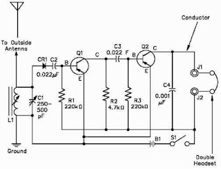
Figure 1 Schematic Diagram
As an example, let us look at a schematic diagram of a two-transistor radio circuit (Figure 1). This diagram, from left to right, shows the components in the order they are used to convert radio waves into sound energy. By using this diagram it is possible to trace the operation of the circuit from beginning to end. Due to this important feature of schematic diagrams, they are widely used in construction, maintenance, and servicing of all types of electronic circuits.
One-Line Diagram
The one-line, or single-line, diagram shows the components of a circuit by means of single lines and the appropriate graphic symbols. One-line diagrams show two or more conductors that are connected between components in the actual circuit. The one-line diagram shows all pertinent information about the sequence of the circuit, but does not give as much detail as a schematic diagram. Normally, the one-line diagram is used to show highly complex systems without showing the actual physical connections between components and individual conductors. As an example, Figure 2 shows a typical one-line diagram of an electrical substation.
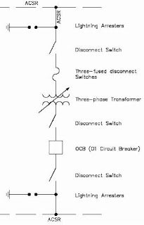
Figure 2 One-Line Diagram
Block Diagram
A block diagram is used to show the relationship between component groups, or stages in a circuit. In block form, it shows the path through a circuit from input to output (Figure 3). The blocks are drawn in the form of squares or rectangles connected by single lines with arrowheads at the terminal end, showing the direction of the signal path from input to output. Normally, the necessary information to describe the stages of components is contained in the blocks.
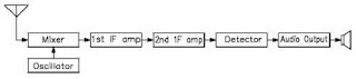
Figure 3 Block Diagram
Wiring Diagram
A wiring diagram is a very simple way to show wiring connections in an easy-to-follow manner. These types of diagrams are normally found with home appliances and automobile electrical systems (Figure 4). Wiring diagrams show the component parts in pictorial form, and the components are identified by name. Most wiring diagrams also show the relative location of component parts and color coding of conductors or leads.
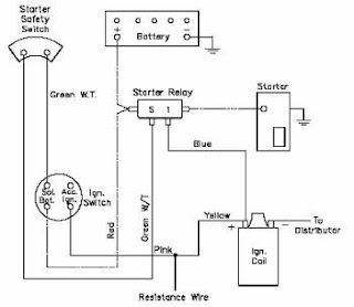
Figure 4 Wiring Diagram
Resistivity
Resistivity is defined as the measure of the resistance a material imposes on current flow. The resistance of a given length of conductor depends upon the resistivity of that material, the length of the conductor, and the cross-sectional area of the conductor, according to Equation (1).
R = rhoL / A……….(1)
where
R = resistance of conductor, ohm
rho= specific resistance or resistivity cm-ohm/ft
L = length of conductor, ft
A = cross-sectional area of conductor, cm
The resistivity(rho) allows different materials to be compared for resistance, according to their nature, without regard to length or area. The higher the value of rho, the higher the resistance. Table 1 gives resistivity values for metals having the standard wire size of one foot in length and a cross-sectional area of 1 cm.
Temperature Coefficient of Resistance
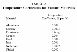
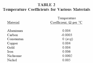
Temperature coefficient of resistance,(alpha), is defined as the amount of change of the resistance of a material for a given change in temperature. A positive value of alpha indicates that R increases with temperature; a negative value of alpha indicates R decreases; and zero alpha indicates that R is constant. Typical values are listed in Table 2.
For a given material, aplha may vary with temperature; therefore, charts are often used to describe how resistance of a material varies with temperature. An increase in resistance can be approximated from equation (2).
Rt = R0+ Ro(alpha.delta.T)………………(2)
where
Rt = higher resistance at higher temperatures
Ro = resistance at 20oC
alpha= temperature coefficient
dT = temperature rise above 20oC
Electric Circuit
Each electrical circuit has at least four basic parts: (1) a source of electromotive force, (2) conductors, (3) load or loads, and (4) some means of control. In Figure 5, the source of EMF is the battery; the conductors are wires which connect the various component parts; the resistor is the load; and a switch is used as the circuit control device.
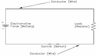
Figure 5 Closed Circuit
A closed circuit (Figure 5) is an uninterrupted, or unbroken, path for current from the source (EMF), through the load, and back to the source.
An open circuit, or incomplete circuit, (Figure 6) exists if a break in the circuit occurs; this prevents a complete path for current flow.
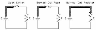
Figure 6 Open Circuit
A short circuit is a circuit which offers very little resistance to current flow and can cause dangerously high current flow through a circuit (Figure 7). Short circuits are usually caused by an inadvertent connection between two points in a circuit which offers little or no resistance to current flow. Shorting resistor R in Figure 7 will probably cause the fuse to blow.
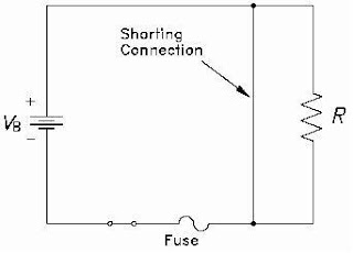
Figure 7 Short Circuit
Series Circuit
A series circuit is a circuit where there is only one path for current flow. In a series circuit (Figure 8), the current will be the same throughout the circuit. This means that the current flow through R1 is the same as the current flow through R2 and R3.
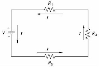
Figure 8 Series Circuit
Parallel Circuit
Parallel circuits are those circuits which have two or more components connected across the same voltage source (Figure 9). Resistors R1, R2, and R3 are in parallel with each other and the source. Each parallel path is a branch with its own individual current. When the current leaves the source V, part I1 of IT will flow through R1; part I2 will flow through R2; and part I3 will flow through R3. Current through each branch can be different; however, voltage throughout the circuit will be equal.
V = V1 = V2 = V3.
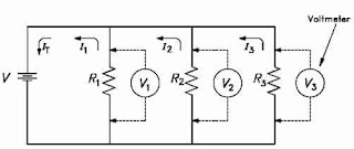
Figure 9 Parallel Circuit
Equivalent Resistance
In a parallel circuit, the total resistance of the resistors in parallel is referred to as equivalent resistance. This can be described as the total circuit resistance as seen by the voltage source. In all cases, the equivalent resistance will be less than any of the individual parallel circuit resistors. Using Ohm’s Law, equivalent resistance (REQ) can be found by dividing the source voltage (V) by the total circuit current (IT), as shown in Figure 9.
REQ = V / It
Summary
The important information concerning basic DC circuits is summarized below. There are four types of circuit diagrams.
- Schematic diagram
- One-line diagram
- Block diagram
- Wiring diagram
• Resistivity is defined as the measure of the resistance a material imposes on current flow.
• Temperature coefficient of resistance, (alpha), is defined as the amount of change of the resistance of a material for a given change in temperature.
• A closed circuit is one that has a complete path for current flow.
• An open circuit is one that does not have a complete path for current flow.
• A short circuit is a circuit with a path that has little or no resistance to current flow.
• A series circuit is one where there is only one path for current flow.
• A parallel circuit is one which has two or more components connected across the same voltage source.
• Equivalent resistance is the total resistance of the resistors in parallel.
Schematic Diagram
Schematic diagrams are the standard means by which we communicate information in electrical and electronics circuits. On schematic diagrams, the component parts are represented by graphic symbols, some of which were presented earlier in Module 1. Because graphic symbols are small, it is possible to have diagrams in a compact form. The symbols and associated lines show how circuit components are connected and the relationship of those components with one another.

Figure 1 Schematic Diagram
As an example, let us look at a schematic diagram of a two-transistor radio circuit (Figure 1). This diagram, from left to right, shows the components in the order they are used to convert radio waves into sound energy. By using this diagram it is possible to trace the operation of the circuit from beginning to end. Due to this important feature of schematic diagrams, they are widely used in construction, maintenance, and servicing of all types of electronic circuits.
One-Line Diagram
The one-line, or single-line, diagram shows the components of a circuit by means of single lines and the appropriate graphic symbols. One-line diagrams show two or more conductors that are connected between components in the actual circuit. The one-line diagram shows all pertinent information about the sequence of the circuit, but does not give as much detail as a schematic diagram. Normally, the one-line diagram is used to show highly complex systems without showing the actual physical connections between components and individual conductors. As an example, Figure 2 shows a typical one-line diagram of an electrical substation.

Figure 2 One-Line Diagram
Block Diagram
A block diagram is used to show the relationship between component groups, or stages in a circuit. In block form, it shows the path through a circuit from input to output (Figure 3). The blocks are drawn in the form of squares or rectangles connected by single lines with arrowheads at the terminal end, showing the direction of the signal path from input to output. Normally, the necessary information to describe the stages of components is contained in the blocks.

Figure 3 Block Diagram
Wiring Diagram
A wiring diagram is a very simple way to show wiring connections in an easy-to-follow manner. These types of diagrams are normally found with home appliances and automobile electrical systems (Figure 4). Wiring diagrams show the component parts in pictorial form, and the components are identified by name. Most wiring diagrams also show the relative location of component parts and color coding of conductors or leads.

Figure 4 Wiring Diagram
Resistivity
Resistivity is defined as the measure of the resistance a material imposes on current flow. The resistance of a given length of conductor depends upon the resistivity of that material, the length of the conductor, and the cross-sectional area of the conductor, according to Equation (1).
R = rhoL / A……….(1)
where
R = resistance of conductor, ohm
rho= specific resistance or resistivity cm-ohm/ft
L = length of conductor, ft
A = cross-sectional area of conductor, cm
The resistivity(rho) allows different materials to be compared for resistance, according to their nature, without regard to length or area. The higher the value of rho, the higher the resistance. Table 1 gives resistivity values for metals having the standard wire size of one foot in length and a cross-sectional area of 1 cm.

Temperature Coefficient of Resistance
Temperature coefficient of resistance,(alpha), is defined as the amount of change of the resistance of a material for a given change in temperature. A positive value of alpha indicates that R increases with temperature; a negative value of alpha indicates R decreases; and zero alpha indicates that R is constant. Typical values are listed in Table 2.

For a given material, aplha may vary with temperature; therefore, charts are often used to describe how resistance of a material varies with temperature. An increase in resistance can be approximated from equation (2).
Rt = R0+ Ro(alpha.delta.T)………………(2)
where
Rt = higher resistance at higher temperatures
Ro = resistance at 20oC
alpha= temperature coefficient
dT = temperature rise above 20oC
Electric Circuit
Each electrical circuit has at least four basic parts: (1) a source of electromotive force, (2) conductors, (3) load or loads, and (4) some means of control. In Figure 5, the source of EMF is the battery; the conductors are wires which connect the various component parts; the resistor is the load; and a switch is used as the circuit control device.

Figure 5 Closed Circuit
A closed circuit (Figure 5) is an uninterrupted, or unbroken, path for current from the source (EMF), through the load, and back to the source.
An open circuit, or incomplete circuit, (Figure 6) exists if a break in the circuit occurs; this prevents a complete path for current flow.

Figure 6 Open Circuit
A short circuit is a circuit which offers very little resistance to current flow and can cause dangerously high current flow through a circuit (Figure 7). Short circuits are usually caused by an inadvertent connection between two points in a circuit which offers little or no resistance to current flow. Shorting resistor R in Figure 7 will probably cause the fuse to blow.

Figure 7 Short Circuit
Series Circuit
A series circuit is a circuit where there is only one path for current flow. In a series circuit (Figure 8), the current will be the same throughout the circuit. This means that the current flow through R1 is the same as the current flow through R2 and R3.

Figure 8 Series Circuit
Parallel Circuit
Parallel circuits are those circuits which have two or more components connected across the same voltage source (Figure 9). Resistors R1, R2, and R3 are in parallel with each other and the source. Each parallel path is a branch with its own individual current. When the current leaves the source V, part I1 of IT will flow through R1; part I2 will flow through R2; and part I3 will flow through R3. Current through each branch can be different; however, voltage throughout the circuit will be equal.
V = V1 = V2 = V3.

Figure 9 Parallel Circuit
Equivalent Resistance
In a parallel circuit, the total resistance of the resistors in parallel is referred to as equivalent resistance. This can be described as the total circuit resistance as seen by the voltage source. In all cases, the equivalent resistance will be less than any of the individual parallel circuit resistors. Using Ohm’s Law, equivalent resistance (REQ) can be found by dividing the source voltage (V) by the total circuit current (IT), as shown in Figure 9.
REQ = V / It
Summary
The important information concerning basic DC circuits is summarized below. There are four types of circuit diagrams.
- Schematic diagram
- One-line diagram
- Block diagram
- Wiring diagram
• Resistivity is defined as the measure of the resistance a material imposes on current flow.
• Temperature coefficient of resistance, (alpha), is defined as the amount of change of the resistance of a material for a given change in temperature.
• A closed circuit is one that has a complete path for current flow.
• An open circuit is one that does not have a complete path for current flow.
• A short circuit is a circuit with a path that has little or no resistance to current flow.
• A series circuit is one where there is only one path for current flow.
• A parallel circuit is one which has two or more components connected across the same voltage source.
• Equivalent resistance is the total resistance of the resistors in parallel.


